DeathFromAbove
My Cat Says AREAR!
oldbikedude said:Spoke nipples
Thats it? I thought there were more.
As you all know, Coffee (Dean) passed away a couple of years ago. I am Dean's ex-wife's husband and happen to have spent my career in tech. Over the years, I occasionally helped Dean with various tech issues.
When he passed, I worked with his kids to gather the necessary credentials to keep this site running. Since then (and for however long they worked with Coffee), Woodschick and Dirtdame have been maintaining the site and covering the costs. Without their hard work and financial support, CafeHusky would have been lost.
Over the past couple of weeks, I’ve been working to migrate the site to a free cloud compute instance so that Woodschick and Dirtdame no longer have to fund it. At the same time, I’ve updated the site to a current version of XenForo (the discussion software it runs on). The previous version was outdated and no longer supported.
Unfortunately, the new software version doesn’t support importing the old site’s styles, so for now, you’ll see the XenForo default style. This may change over time.
Coffee didn’t document the work he did on the site, so I’ve been digging through the old setup to understand how everything was running. There may still be things I’ve missed. One known issue is that email functionality is not yet working on the new site, but I hope to resolve this over time.
Thanks for your patience and support!
oldbikedude said:Spoke nipples
 , but I jump all over the place so I could have imagined it.
 I think I'll have a drink while I ponder.
 Thanks OBD!
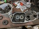
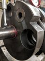
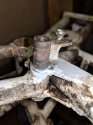
 Then once it was assembled I checked the transmission, I changed the 4th and 5/6 gears on the clutch shaft. Shifts fine. Then I noticed the crank wont spin! WTF!!
  So start rooting around and see the crank I touching the inside of the right case. A little further investigation and I see the crank bearings in the left case are not touching the plate by about 2mm. I thought I heard them touch down when I dropped them in!! Apparently not. So apart she comes for a reheat and tap to touch the plate. An inspection of the crank shows a light rub mark, though the tuning is not lost. Just a refresher..... MAKE SURE THE BEARINGS ARE ALL THE WAY HOME BEFORE YOU ASSEMBLE THE MOTOR! Lesson learned.
Mallets are for tuning a crank, not installing a crank.GaryM said:Huskydogg used to tap with a mallet
 After spending all that time tuning to get it as perfect as you as you can, why smack the thing on the side with a mallet?
I should have noticed that, but I didn't.GaryM said:Sometimes cranks are pulled a bit off center.
 Since I've been wearing these cheater glasses I have been missing a lot.
  :oldman:") I stepped off a ladder from the second rung and almost killed myself.
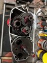
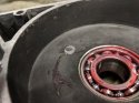
I stepped off a ladder from the second rung and almost killed myself.If it weren't for the slight drag when spinning the crank, (I know I said it wouldn't spin, not freely anyhow) I would have never caught it. I checked my build book and found when I built the 450 the rotor was dragging when I installed the ignition. The crank was pulled too far to the left. I don't know if it was the stubs installed too far into the cheeks or the taper on the rotor but I rebuilt the crank twice to the book and the bearings were seated to the stop plate, it was still marginal. So that crank is slightly off center in the cases to make up for the rotor clearance. 1MM is not a lot of clearance as far as I am concerned.surprize said:nice catch

 ). That is the way I have been doing it. I think I will change to the latter method to get the crank in the perfect position as there is not a lot of room in the crank cavity. Always learning hurts.
Cases at temp, ok. The only tool I have is me.GaryM said:You can also tap the bearing to seat them
I can't afford the good tools, that's why I screw things up!
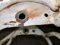
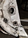
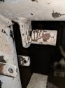
I just left them in. The frame was blasted and powdercoated. I did have to use some fine sandpaper to remove enough powedercoat material to get the shock bushings to slide onto the mounts. Turned out fine.The parts list shows the upper shock mounts are removable. I'm afraid to damage the hole by removing them for plating, any ideas?
Thanks Todd, I left them in also, but I have some hi-temp tape to mask them and every other area I don't want powder to stick. Chrisarbortodd2 said:I did have to use some fine sandpaper to remove enough powedercoat material
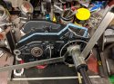
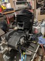
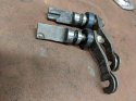
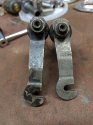
regardless, i would use the longer one, which might be a four stroke piece?..will help ease clutch pull. just have to insure you use the magura power levers to insure complete clutch engagement and the center push rod adjusted right..both arms are the "z' style which are improvement over the original flat arm. better angle to be pulled by the cable which is mounted higher than the arm. i think the z style is always seen on liquid bikes only.I finally got the piston and cylinder installed. The frame is at blasting and the powder should be here by Monday. I still have to blast the fork lowers and axle plates, I am also thinking of using the powder on the tank. I am still looking for a chain tensioner and chain guide. So if you have one to spare I'm interested. I also have two declutching rods and can't remember which was original or which came with the replacement case half. If you know please chime in. Thanks Chris
Thanks, I'll look for one of the newer stepped style rods and use the longer arm. I hope the push rod isn't too bad, is there a measurement for that, I didn't see it in the manual. Thanksjustintendo said:both actuating cams are really whupped however