-
Hi everyone,
As you all know, Coffee (Dean) passed away a couple of years ago. I am Dean's ex-wife's husband and happen to have spent my career in tech. Over the years, I occasionally helped Dean with various tech issues.
When he passed, I worked with his kids to gather the necessary credentials to keep this site running. Since then (and for however long they worked with Coffee), Woodschick and Dirtdame have been maintaining the site and covering the costs. Without their hard work and financial support, CafeHusky would have been lost.
Over the past couple of weeks, I’ve been working to migrate the site to a free cloud compute instance so that Woodschick and Dirtdame no longer have to fund it. At the same time, I’ve updated the site to a current version of XenForo (the discussion software it runs on). The previous version was outdated and no longer supported.
Unfortunately, the new software version doesn’t support importing the old site’s styles, so for now, you’ll see the XenForo default style. This may change over time.
Coffee didn’t document the work he did on the site, so I’ve been digging through the old setup to understand how everything was running. There may still be things I’ve missed. One known issue is that email functionality is not yet working on the new site, but I hope to resolve this over time.
Thanks for your patience and support!
You should upgrade or use an alternative browser.
125-200cc Part 2: Installation of the WB165 Kit
- Thread starter MattR
- Start date
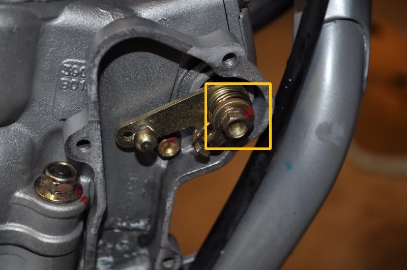
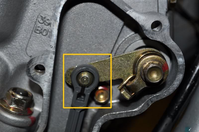
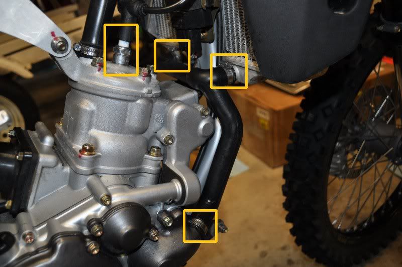
Next, the upper PV linkage is attached. Here is the orientation of the parts. When tightening the bolt, it helps to use a wrench/pliers to hold the outer spring tab (to prevent rotation).
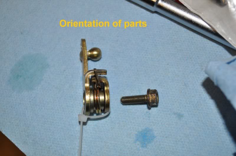
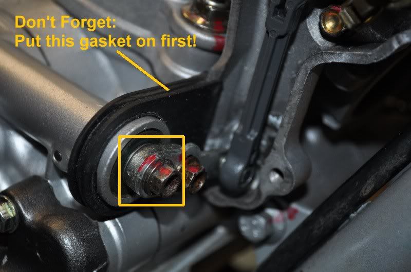
TIP: DON’T FORGET TO INSTALL THE COVER GASKET BEFORE ATTACHING THE LOWER LINK.
I made this mistake and had to disassembly to put the gasket back on… oops!
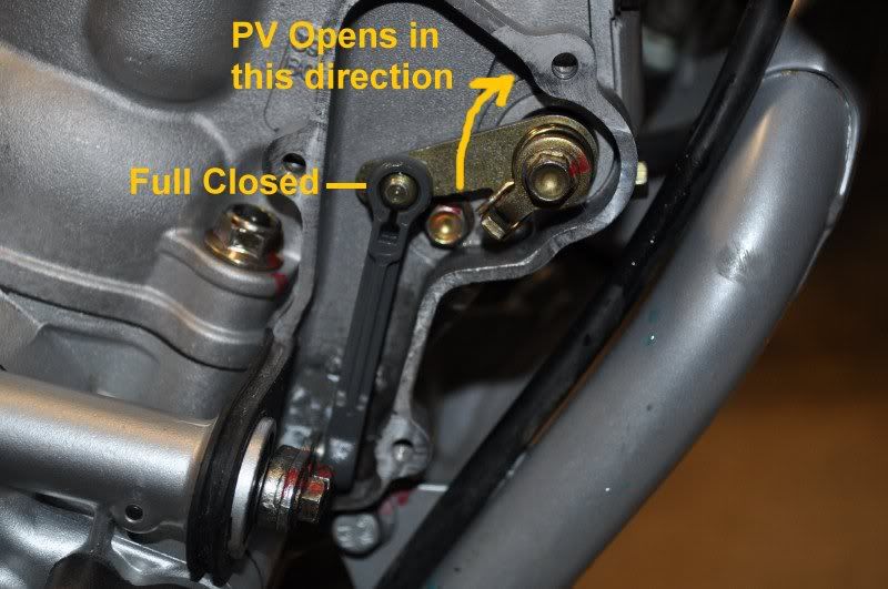
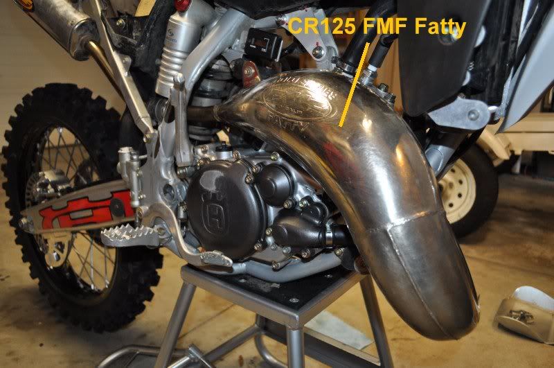
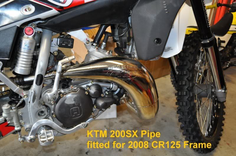
I temporarily installed my CR125 FMF Fatty pipe and left the PV cover off (from previous step above). I wanted to make sure the PV was operating correctly after starting my bike.
I am using Walt’s suggestions for initial break-in:
1) Start it and let it idle for ~10 minutes. Vary the rpms slightly throughout. Let it cool completely.
2) Repeat with slightly more variance of the throttle for ~10 minutes. Let it cool completely.
Matt’s comment: During this heat cycle, I checked to see if my PV was starting to open properly. I didn’t get stupid with WFO throttle… just enough rpm to see the linkage move to begin opening the PV.
3) Now go for a gentle ride keeping the engine rpms below the power valve opening ~10-15 minutes. Let it cool and then take a compression test. Note: engine should be warm with taking the compression test. This will be your base line for top end health.
4) Now go ride but try to keep away from extended WOT runs for the first 30-60 minutes. It would good to do a throttle chop plug check at some point early in this ride to verify your jetting.
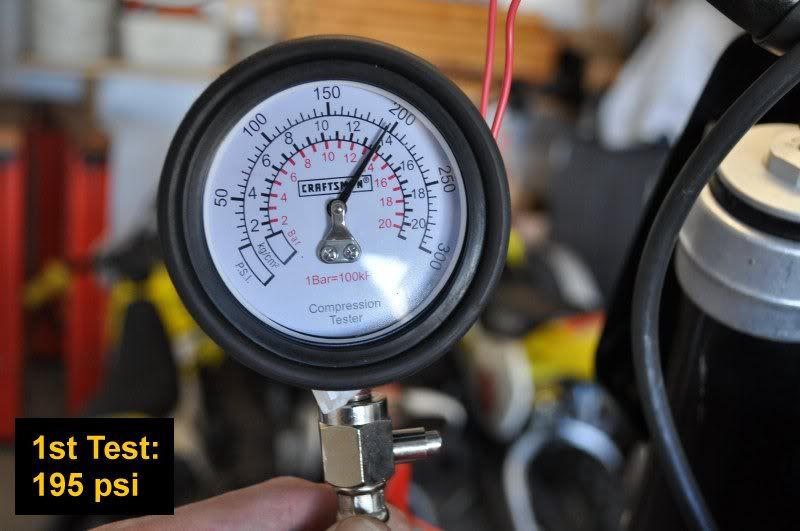
I ran my bike briefly until engine was warm.
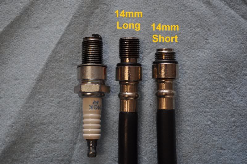
Installed my Craftsmen compression tester with 14mm long attachment.
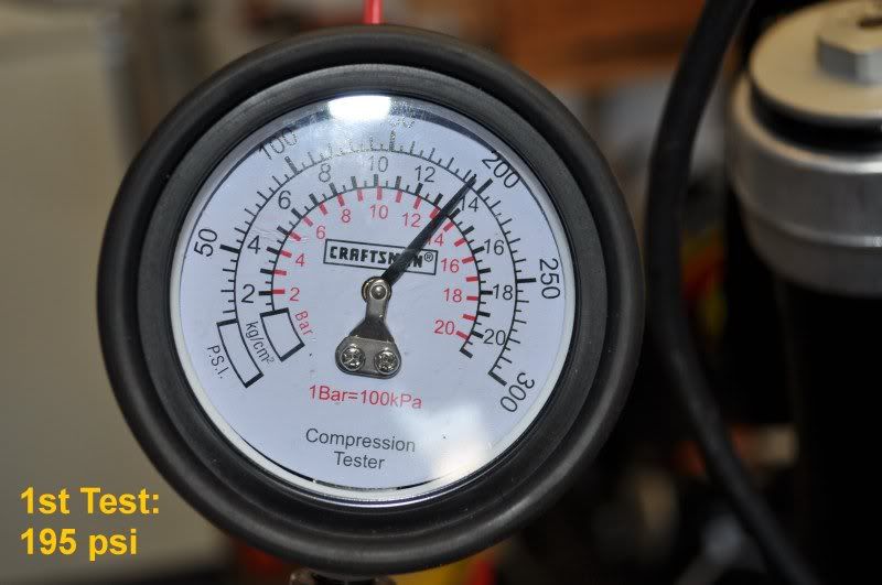
Using WFO throttle with 10 strong kicks.
1st trial = 195 psi
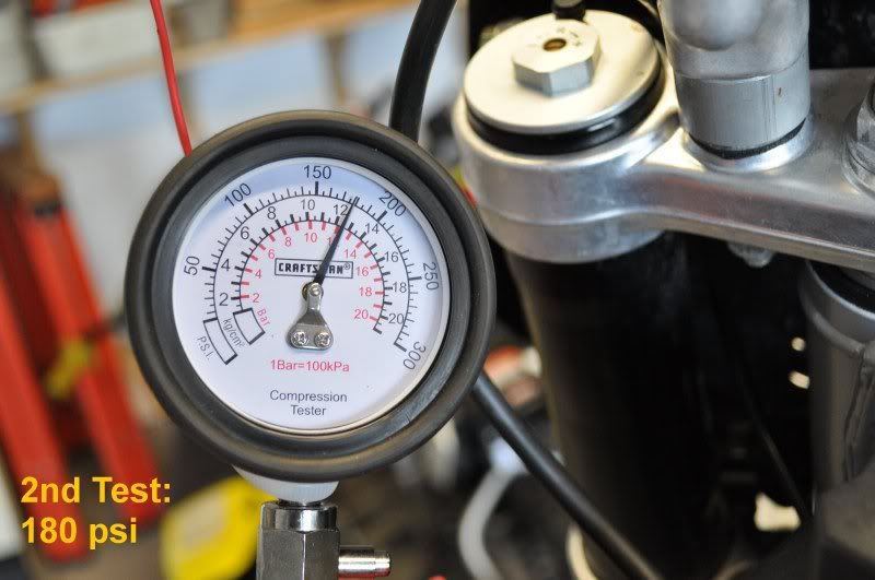
2nd trial = 180 psi
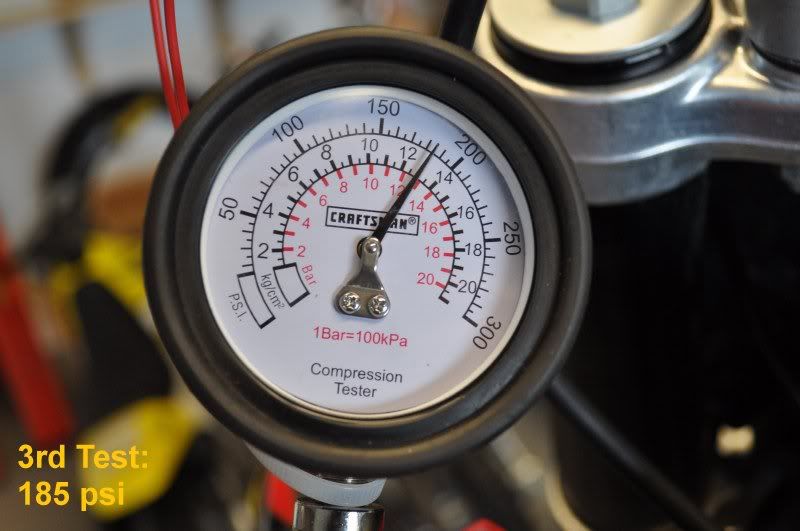
3rd trial = 185 psi
NOTE: Later, I will test it again after my first “real” ride (step #4 from above).
Here is a comparison between 14mm long and 14mm short attachments. The 14mm long has equal length to spark plug and was used for my tests.
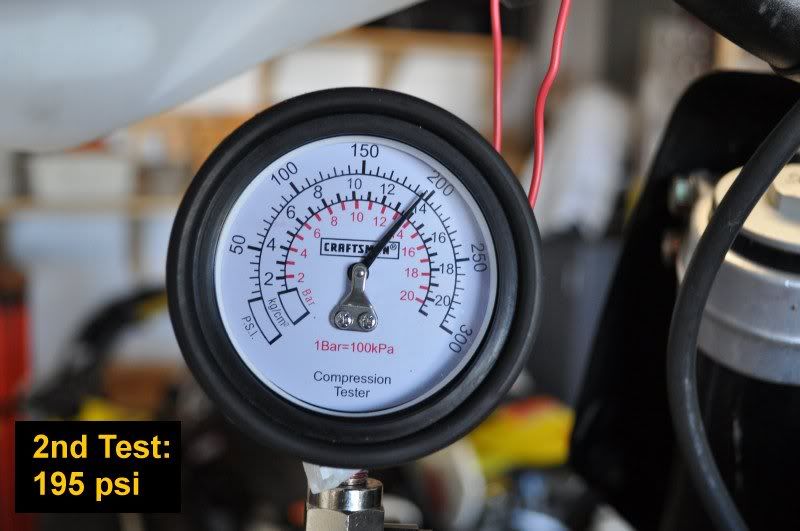
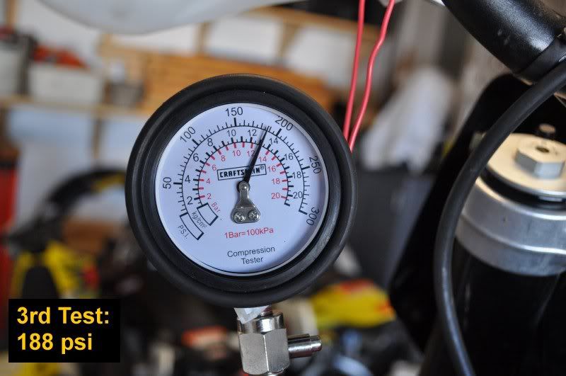
Here are pictures of my compression test results:
I did my first real ride (approx. 2 hrs) and used the full throttle range. After I got back home, I ran another compression test to compare with my prior results.
I used the same procedure as last time...
I ran my bike briefly until engine was warm.
Installed my Craftsmen compression tester with 14mm long attachment.
Using WFO throttle with 10 strong kicks.
1st trial = 195 psi
2nd trial = 195 psi
3rd trial = 188 psi
wallybean
Mini-Sponsor
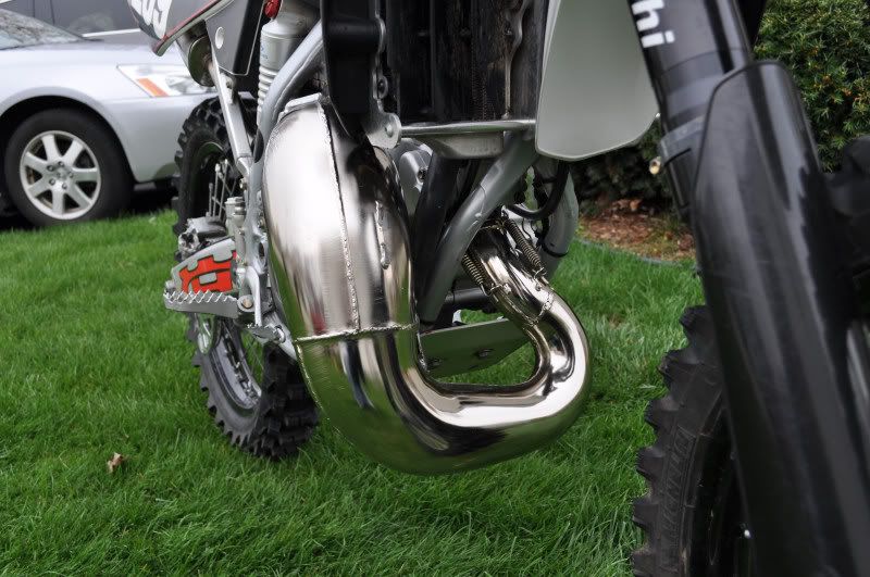
I thought the same thing when I first mounted mine/Kelly's. Rode in some seriously rocky gardens and narrow mountain crap holes. Never made a real dent in it.
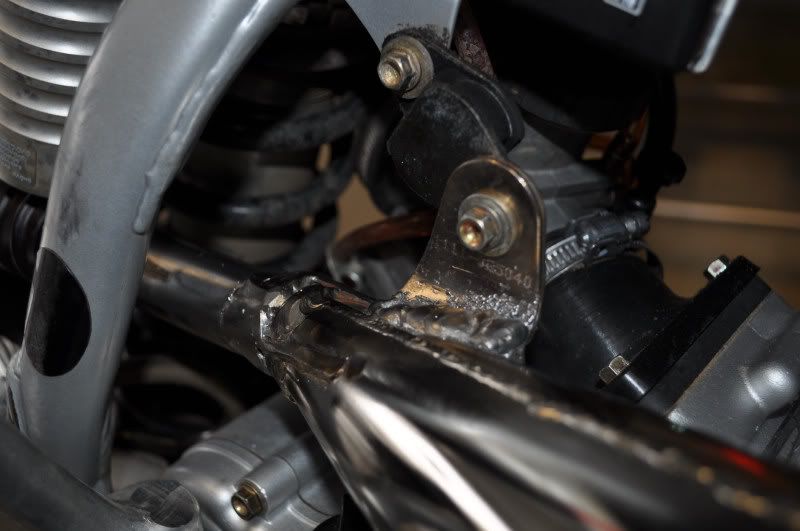
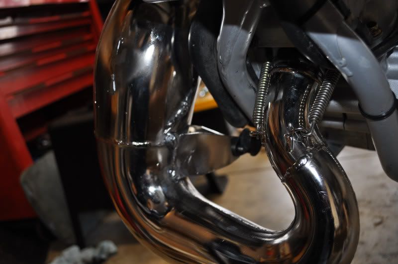
 The pipe guard does help this pipe alot but I think it isn't in the way as much as it looks. Lots of rocks, downfall trees and various crap with no dents yet. Maybe it is the extra strong mounting and welding.
Matt,
You should have been a surgeon. Fantastic posting and should be a mandatory read before doing a re-build for anyone that is worried about the process. Thank you for all your effort and time.

wallybean
Mini-Sponsor
I went out and compared my 360 pipe location to the fmf 200 fatty on the 125 and the 360 pipe is far more exposed on the bottom. Mostly because the pipe is tucked in tighter to the motor and farther from the front wheel. The fatty on the 125 where it is lowest is also pretty close to the front tire so most of the trail crap is beyond the pipe and nails the skid plate/frame rather than the pipe. Sounds good in theory.
